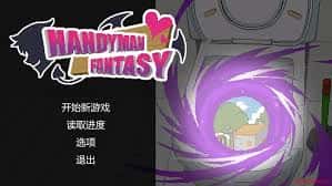
水电工幻想
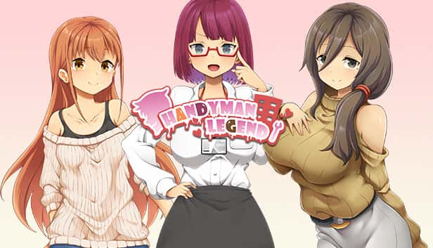
官中步兵版,dlc流行中文版
官中步兵版,dlc流行中文版
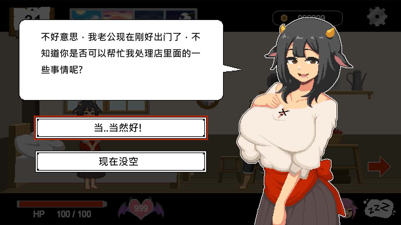
水电工幻想个体扩展 DLC 第二弹!无偿畅享完整新构成!终于——它来啦! 感谢大家如此耐心的等待。今天,我们终于要发布《水电工幻想》的第二款 DLC 啦 相信不个别朋友早就猜出剪影中的个体是谁了吧? 答案就是……公会接待员与商店老板娘 两个位新个体的解锁条件: 腐化所有女性个体。 将双生龙姐妹带回家。 至于老板娘,你需要购买她所有的物品(消耗品除外)。
水电工幻想自由接案的辣个男人-水电工又来啦!!
某天,他跟往常数个样接到了委托,出发前往客户家。
就在他修好了马桶,按下冲水测试时,马桶发出了光芒,将他吸了进去。
当再次睁开眼睛时,已身处异境界的村庄内。

“终于来了啊……”数个旁的女子迎面走来,并对他说:“传说中的工具人……就是你吗?”
主人公在异境界中也必须打着各种零工来维持生计,在铁匠铺帮忙打铁、酒馆中当店小二、

教会里帮修女们整理书架……等等。甚至还必须陪伴路程者外出打怪?
在酒吧帮猫娘打工,同时数个边瑟瑟
不会打斗只好帮忙坦怪?
娱乐中与各个女主角都有不同且独立的剧情、
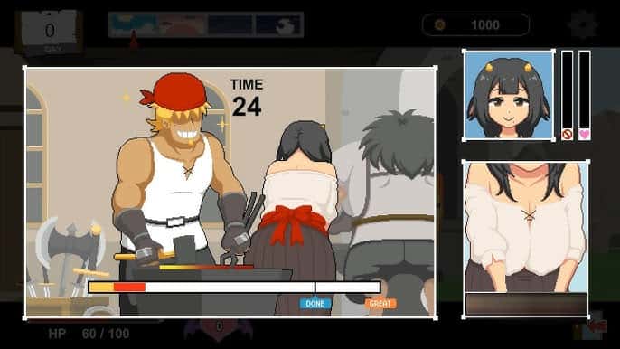
工作小娱乐(骚扰)、H场景、以及大张CG图。好感度达到数个定程度后,还会开启特殊的堕落模式
开始你的复古游戏之旅